
Microwave Test Fixture |
||||||||||
 |
||||||||||
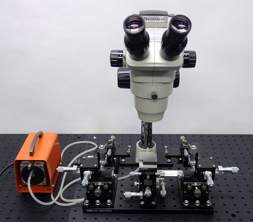
| This system is a microwave test fixture for performing high-frequency measurements on a DUT (Device Under Test). The DUT may be a small circuit board, a microwave component, or a millimeter-wave device on a wafer, and it is held stably and securely in the measurement position by a vacuum chuck table. During measurement, a high-frequency GSG probe (Ground-Signal-Ground configuration) is brought into contact with the electrode pads on the DUT, allowing frequency characteristics such as S-parameters to be evaluated. A GSG probe has a signal line (S) in the center with ground lines (G) on either side, enabling measurements with reduced noise and crosstalk while maintaining a characteristic impedance of 50 Ω. A dedicated positioner is provided for the probe, featuring a rotation adjustment mechanism in addition to X, Y, and Z axes. This allows the GSG probe to be precisely aligned with the DUT electrodes so that each contact at the probe tip lands optimally on its corresponding pad. Especially in the high-frequency range, the probe contact condition directly affects the measurement results, making fine rotational adjustment essential. This ensures the symmetry and matching of the signal and ground lines, minimizing measurement errors in parameters such as return loss and insertion loss. |
||||||||||
■Specifications |
||||||||||
|
||||||||||
*Specifications and appearance are subject to change without notice for improvement. |
||||||||||
■What Is a GSG (Ground-Signal-Ground) Probe? |
||||||||||
| A GSG probe is a precision probing tool used for high-frequency characterization and on-wafer measurement, designed especially for measurements in the RF and microwave ranges. GSG refers to a configuration in which a signal line (Signal) is placed in the center, with ground lines (Ground) arranged symmetrically on either side. This configuration provides a signal return path on both sides of the probe, delivering excellent high-frequency transmission characteristics and a stable measurement environment. The probe is designed to maintain a highly accurate match with the 50 Ω characteristic impedance of coaxial lines, enabling broadband, low-reflection signal transmission from several GHz to several tens of GHz. The probe tip makes direct contact with tiny electrode pads on the wafer, supporting high-precision S-parameter measurements and DC characterization. The contact spacing (pitch) of the probe can generally be selected from 100 μm, 150 μm, 200 μm, and other options, allowing flexible adaptation to various device structures. The most important feature of a GSG probe is that its structure suppresses electromagnetic interference (EMI) and stabilizes the return current path. This improves measurement repeatability and enables reliable data acquisition when characterizing high-frequency circuits and semiconductor devices. In addition, when used together with a dedicated calibration substrate (SOLT, TRL, etc.), a high-precision interface with a vector network analyzer can be established. GSG probes are widely adopted as an indispensable measurement tool in the development and evaluation of advanced electronic devices, such as RF transistors, passive components, millimeter-wave chips, and 5G/6G-related devices. |
