
Manual Probe Station for Optical Characterization |
||||||||||||||
 |
||||||||||||||
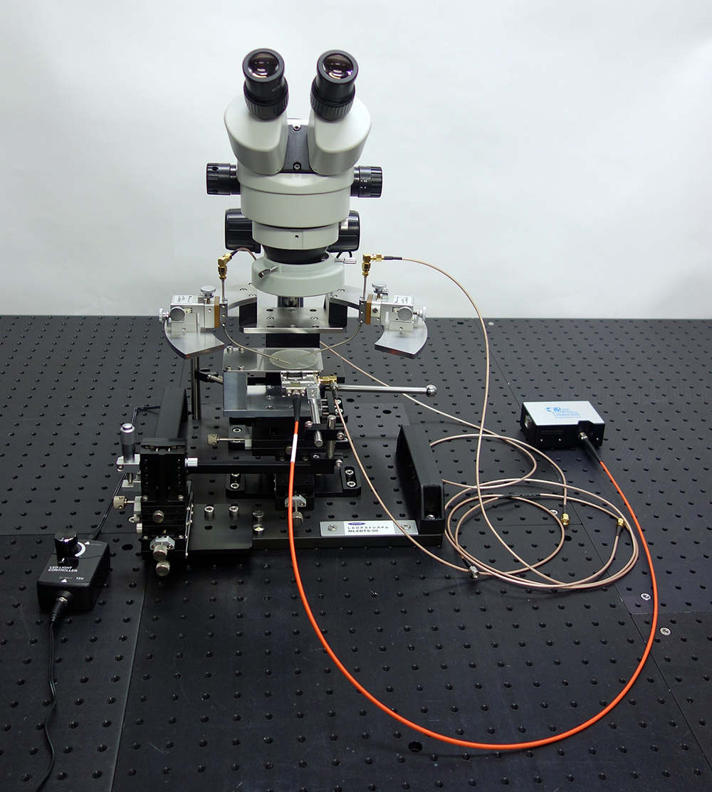
| This manual probe station is designed to measure the I-V-L (current-voltage-light output) characteristics and emission spectra of back-emitting optical semiconductor devices. A probe station is a system that performs electrical and optical testing at the wafer level by bringing probes (needles) into contact with the electrodes of devices such as ICs, LSIs, LEDs, and LDs fabricated on a wafer. A key feature of our probe stations is their ability to measure optical characteristics, allowing the optical properties of light-emitting devices such as LEDs, laser diodes, and VCSELs to be evaluated at the wafer level. The system consists of the microscope, probe station, photodetector, optical probe, and other components needed to observe the wafer through a microscope, place the needles on the electrodes, apply current, and measure the optical characteristics of light-emitting devices (I-V, I-L, V-L, and spectral measurements). | ||||||||||||||
■Specifications |
||||||||||||||
|
||||||||||||||
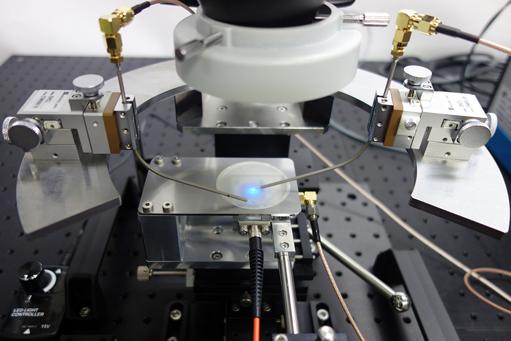
■Photo During Blue LED Measurement |
||||||||||||||
 |
||||||||||||||
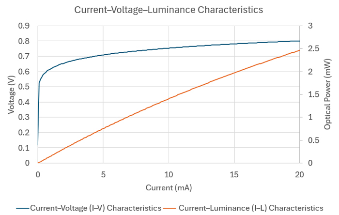
■I-V-L Characteristics of a Near-Infrared LED |
||||||||||||||
 |
||||||||||||||
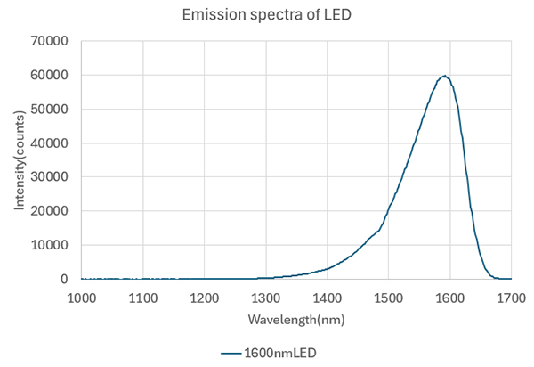
■Emission Spectrum of a Near-Infrared LED |
||||||||||||||
 |
||||||||||||||
*Specifications and appearance are subject to change without notice for improvement. |
||||||||||||||
■What Is a Manual Probe Station? |
||||||||||||||
|
A manual probe station is a measurement system for evaluating the electrical characteristics of semiconductor devices and electronic components, such as current-voltage (I-V) and capacitance-voltage (C-V) characteristics. Probe needles are manually and precisely brought into contact with the tiny electrodes on the device under test, and connected to various measuring instruments to apply signals and acquire responses. The system mainly consists of a sample stage, platen, positioners, probe needles, and a base plate. The sample stage holds samples such as wafers and chips, and a manual XY stage beneath it allows the device under test to be moved in fine increments. This makes it possible to measure many devices on a wafer in succession. The platen is a stage that can be raised and lowered and carries the positioners that hold the probe needles. The positioners are mechanisms for fine adjustment of the probe needle position along the X, Y, and Z axes. Used together with a stereo microscope, they enable precise alignment of the needle tips with the electrodes. To take a measurement, first move the platen to the bottom position (home position) and operate the positioners to align the probe needles precisely over the electrodes. Then bring the probe needles into contact with the electrodes and perform the measurement. After the measurement, raise the platen to lift the probe needles off the electrodes, and operate the XY stage to move the sample to the electrode position of the next device. Then lower the platen again and carry out the next measurement. By repeating this sequence, multiple devices on a wafer can be measured efficiently and continuously. Thanks to their simple structure, ease of operation, and relatively low cost of introduction, manual probe stations are widely used in many settings, including research and development, prototype evaluation, in-process inspection, and failure analysis. Their configuration is also highly flexible: the number of probes and the instrument setup can be changed to suit the application, making them adaptable to a wide range of measurement needs. |
||||||||||||||
■About the I-V-L Characteristics of LEDs |
||||||||||||||
|
The I-V-L characteristics of an LED are key indicators for comprehensively evaluating the electrical and optical performance of an LED device. They refer to three relationships: the I-V characteristic (current vs. voltage), the I-L characteristic (current vs. light output), and the V-L characteristic (voltage vs. light output). The I-V characteristic is obtained by measuring how the current changes as voltage is applied to the LED, revealing basic electrical properties of the device such as the threshold voltage and internal resistance. It is characterized by the nonlinear response typical of diodes, in which current begins to flow sharply above a certain voltage, and is used for evaluating initial characteristics and identifying defects. The I-L characteristic shows the relationship between the current supplied to the LED and the resulting light output, and is used to evaluate the rise of the light output, slope efficiency, and luminous efficiency. From this characteristic, it is possible to select the optimum drive current and to understand how the light output saturates or degrades under overcurrent conditions. The V-L characteristic shows the relationship between voltage and light output, and is generally derived by combining the I-V and I-L measurement results. It provides insight into power efficiency under actual operating conditions (e.g., mW/W or lm/W) and is useful for energy-saving design and for identifying drive conditions that minimize heat generation. Accurate measurement and analysis of these I-V-L characteristics play an extremely important role in evaluating LED device performance, optimizing product development, and supporting quality control and reliability testing. |
||||||||||||||
