Manual Probe Station for Optical Characterization
MMP-ILS01 |
 |
| |
| |
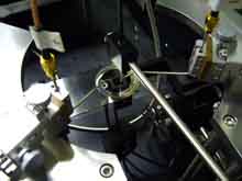
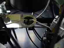
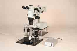
| This electrical and optical probing system is designed for wafer-level measurement of the optical characteristics of light-emitting devices, including LEDs, laser diodes, and VCSELs. While observing the wafer through a microscope, probe needles are brought into contact with the electrodes to supply current to the devices. The system comprises the microscope, probe station, photodetectors, optical probes, and other components needed for I-V, I-L, V-L, and spectral measurements. |
| |
■Features |
- High-resolution stereo microscope simplifies probing.
- The optical fiber probe for spectral measurements can be positioned close to the emission point, enabling measurement of weak light.
- Optical characteristics can be measured from both above and below the sample.
- The manipulators have magnetic mounting plates and can be secured at any desired position on the ring plate.
- A high-sensitivity camera enables real-time observation of light emission.
- A lever allows the probe needles to be raised and lowered easily together with the ring plate.
|
|
■Specifications |
Sample Stage |
| Sample Size |
Up to 30 mm diameter |
| Measurement Surface Plate Material |
Synthetic quartz |
| Sample Stage Travel |
X-axis: 60 mm Y-axis: 100 mm |
| Travel per Handle Rotation |
X-axis: Coarse 20 mm, fine approximately 2.6 mm
Y-axis: Coarse 18 mm, fine approximately 2.3 mm |
|
Manipulators |
| Probe Needles |
Tungsten carbide needles |
| Travel |
10 mm per axis (X, Y, Z) |
| Travel per Rotation |
500 μm per axis (X, Y, Z) |
| Carrier |
Equipped with a magnetic mounting plate |
| Number of Manipulators |
3 |
| Ring Plate Material |
Magnetic stainless steel (SUS) |
|
Lower Detection Stage |
| Detector Switching Travel |
60 mm |
| Positioning Travel |
X/Y: 13 mm Z: 10 mm |
| Positioning Micrometer Graduation |
10 μm/division |
|
Upper Detection Stages |
| Positioning Travel |
X/Y: 13 mm Z: 10 mm |
| Positioning Micrometer Graduation |
10 μm/division |
| Quantity |
2 |
|
Optical Intensity Detector |
| Spectral Response Range |
190–1100 nm |
| Photosensitive Area |
10 × 10 mm |
| Responsivity |
0.12 A/W (typical at 200 nm) |
| Signal Output |
Selectable: 100,000 V/A, 76,700 V/A, 50,000 V/A, 24,800 V/A, 10,700 V/A (typical) |
| Number of Detector Heads |
1 upper / 1 lower |
| Power Requirements |
100 V AC, 0.6 A |
|
Optical Fiber Probes for Spectral Measurements |
| Fiber Type |
Pure silica step-index (SI) fiber |
| Wavelength Range |
200 nm–900 nm |
| Core Diameter |
600 μm |
| Fiber Terminations |
Upper fiber: 3 mm diameter × 30 mm sleeve at one end, SMA connector at the other
Lower fiber: SMA connectors at both ends |
| Quantity |
1 upper / 1 lower |
|
Microscope |
| Observation Magnification |
7×–115× |
| Zoom Ratio |
16.4 |
| Field of View |
31.4–1.9 mm diameter |
| Objective Working Distance (W.D.) |
60 mm |
| Objective Numerical Aperture (N.A.) |
0.15 |
| Eyepieces |
10×, field number 22 |
| Optical System |
Galilean parallel optical system |
| Focusing Mechanism |
Rack-and-pinion mechanism with roller guides |
| Focusing Travel |
80 mm |
| Travel per Coarse Focus Knob Rotation |
21 mm |
| Illumination |
Coaxial epi-illumination with a halogen lamp |
| Microscope Unit Travel |
Front/back: 220 mm, vertical: 210 mm, rotation: 360° |
|
High-Sensitivity Camera for Emission Observation |
| Effective Pixel Count |
12 megapixels |
| Image Sensor |
1/2.33-type CCD |
| Optical Zoom |
26× |
| LCD Monitor |
2.7-inch TFT color LCD |
| Shutter Speed |
1/2–1/2000 second (Bulb: Up to 8 minutes) |
| Still Image Recording Format |
JPEG (DCF compliant), DPOF compatible, Exif 2.2, PRINT Image Matching III |
| Interfaces |
USB, NTSC, HDMI |
|
| *Specifications and appearance are subject to change without notice for product improvement. |